The current implementation / handling of critical azimuth and zenith angles for ICON wedges:
For a given Wedge Element out of an ICON Mesh, we define the side face which is most illuminated by the sun as the Base-face.
In clockwise rotation we then have a left and right face.
E.g. in the following example:
- base-face -> 3
- left-face -> 4
- right-face-> 5
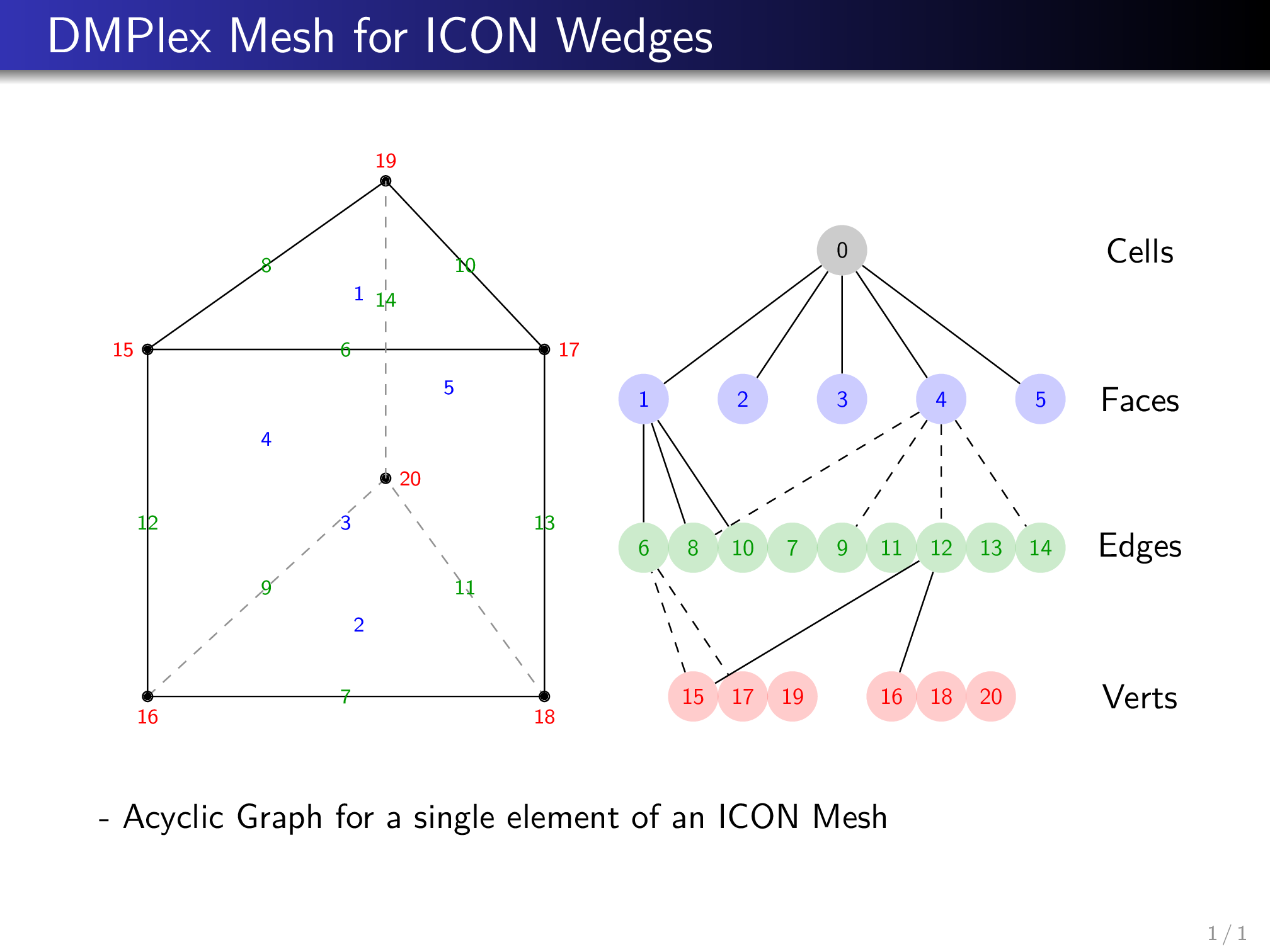
The local azimuth and zenith is then defined in the local coordinate system which spans:
where \(n_i\) are the inward (to the wedge center) facing face normals. Note that \(\vec e_y\) is just the projection of \(\vec n_2\) onto face(1).
Further, we define the horizontal length of the upper edge on the baseface to be 1, i.e. the distance between vertices A (15) and B (17). The relative coordinate of the point C (19) then accounts for the distortion of the wedge. The ICON mesh is additionally distorted vertically, i.e. the face surface of face(1) is larger than the surface of face(2) because the geometry is a 2D mesh of a spheres surface projected outwards from the center of the sphere.
This geometry introduces some interesting caveats into the raytracing approach that we use in the TenStream framework. In the portrayed case that we look at the wedge as in the figure atop, we have the local azimuth \(\phi = 0\) and the zenith angle \(\theta \approx 60^\circ\)
Assuming the direction of the sun is the same as the viewers perspective, it is easy to determine that light will shine in from face(1) and face(3) and will exit through face(2), face(4) and face(5). We label these:
- Top face -> Source
- Base face -> Source
- Bottomface -> Destination
- Left face -> Destination
- Right face -> Destination
If you imagine now that the zenith angle \(\theta =0\), we have only one source face left (face(1)) and all other faces are radiation destinations. Also, if we go towards azimuth angles \(\phi > 0\), i.e. we rotate the wedge counter clockwise there comes a point where face(4) will become a source too. The critical azimuth \(\phi_{crit}\) at which this change from destination to source will happen depends on the distortion due to the coordinates of the point C (vertex19) as well as on the vertical distortion.
Further, there is another interesting value for the azimuth at which the next (e.g. the left face) will be considered as base face. This yields a bound for our parameter study. As mentioned earlier, there is also a critical value for the zenith angle \(\theta_{crit}\) at which we have a change from source to destination. Because these critical angles and hence points in TenStream LookupTables are not orthogonal to the other dimensions such as the C point coordinates we would need a gigantic amount of sampling points which is unfeasible due to the dramatic increase in memory.
However, accounting for these jumps is of utmost importance because of the relationship between the various wedges. When we couple the elements in a large equation system, the transport coefficients of two neighboring cells have to match their assumptions about the intermediate face, i.e. if radiation is transported from left to right or from right to left. If these do not fit together, we loose or introduce radiation and get plain wrong results.
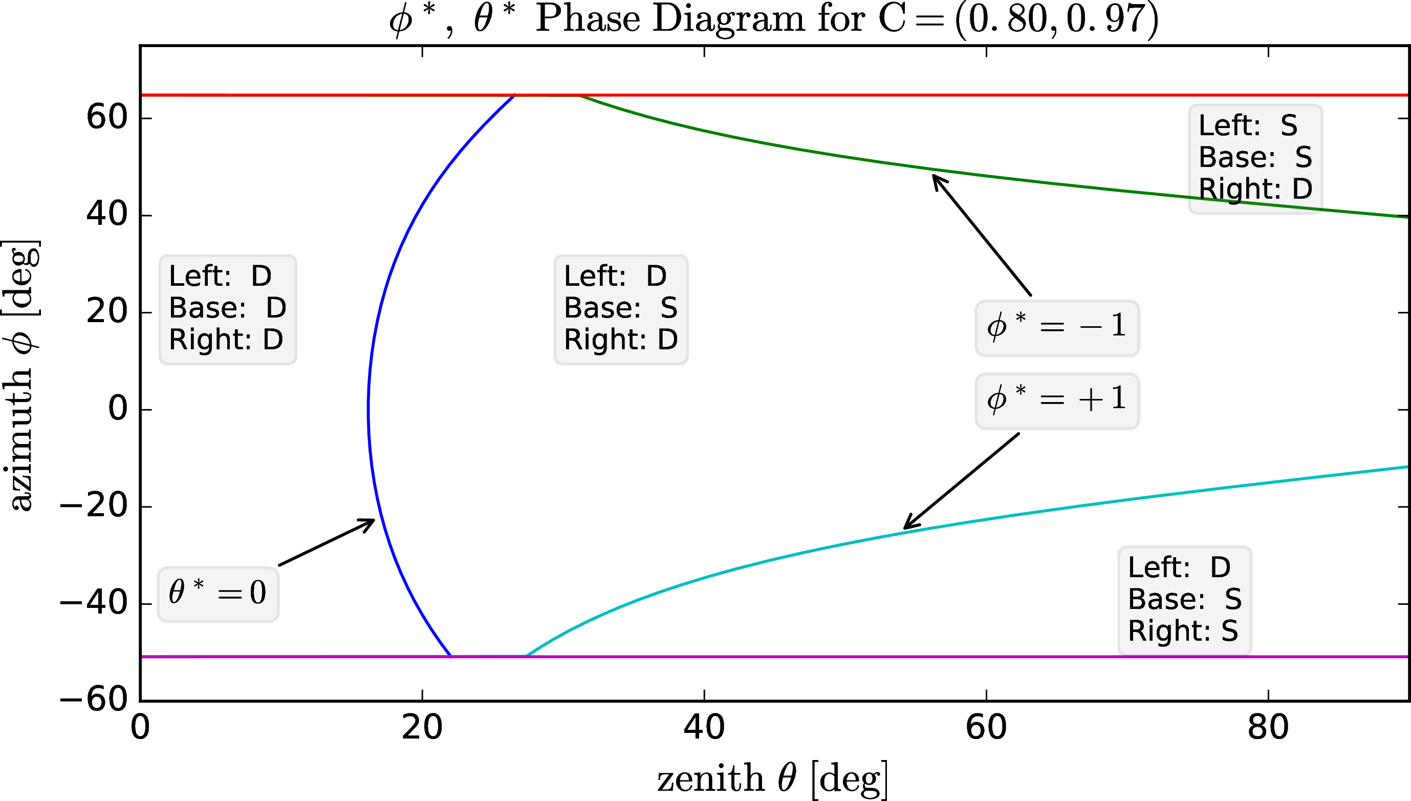
To fix this issue we opt to introduce 2 new dimensions instead of \(\phi\) and \(\theta\). Namely a parameterized version of \(\phi^*\) and \(\theta^*\), where
In brackets we give exemplary values for an equilateral triangle
- \(\phi^* = -2\) - lower bound for azimuth (\(60^\circ\))
- \(\phi^* = -1\) - critical value where right face becomes source (\(30^\circ\))
- \(\phi^* = 1\) - critical value where left face becomes source (\(-30^\circ\))
-
\(\phi^* = 2\) - upper bound for azimuth (\(-60^\circ\))
-
\(\theta^* = -1\) - lower bound for zenith (\(0^\circ\))
- \(\theta^* = 0\) - critical point where base face changes between src and destination
- \(\theta^* = 1\) - upper bound for zenith (\(90^\circ\))
Source/Destination Phase Diagram for an ICON Wedge Element
The Following graph depicts the critical angles at which phase changes occur, i.e. at which angles occur changes between source and destination. Note that the distortion for this example is rather extreme. This is for a wedge that has bottom and top face spherical radii [1,10]. For normal ICON meshes we have radii aspects of [1km / 6374km] and for those, the blue line moves far to the left, e.g. \(\theta_{crit} = 0.001^\circ\).